Design guide for components with threads and counterbores
Useful information about the threading and counterboring process, how to properly prepare your files for them, capabilities, and limitations of our process.
Content
Threading
-
Threading process >Threading process >
-
Preparing your file for threading >Preparing your file for threading >
-
Capabilities of the threading process >Capabilities of the threading process >
Counterboring
-
Counterboring process >Counterboring process >
-
Preparing your file for counterboring >Preparing your file for counterboring >
-
Capabilities of the counterboring process >Capabilities of the counterboring process >
Click on the topics to access them.
Check out our
Threading Process
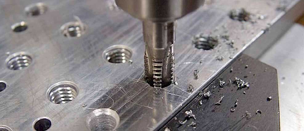
Threading in sheet metal involves creating a thread in a previously drilled hole, allowing for the fastening of screws and other threaded components. At LaserBoost, we perform this process using tap tools, ensuring precision and strength in each thread without deforming the material.
> Preparing your file for threading
Preparing your files correctly for threading not only optimizes the process but can also significantly speed up production time.
Preparation of 2D files with threading
To correctly generate the 2D file intended for producing a flat part with threading, it’s essential to draw the threaded hole as if it were a conventional hole, without including marks or indications about the threading. The diameter of this hole should be correct for creating the thread, known as the “pre-thread hole” (measured according to the thread process capabilities table below). Next, select the threading process, specifying both the Thread Size and Quantity of threads for the part, to ensure precise and efficient manufacturing. You can add comments or documents to provide more information about which holes need threading.
Preparation of 3D files with threading
To correctly generate the 3D file intended for producing a flat or folded part with threading, it’s essential to draw the threaded hole as if it were a conventional hole, without including the 3D thread features. The diameter of this hole should be correct for creating the thread, known as the “pre-thread hole” (measured according to the thread process capabilities table below). Next, select the threading process, specifying both the Thread Size and Quantity of threads for the parts, to ensure precise and efficient manufacturing. You can add comments or documents to provide more information about which holes need threading.
> Capabilities of the threading process
At LaserBoost, we utilize the thread tapping method, employing specialized machinery and a specific configuration for each successful threading process.
Our thread production model adheres to the Metric system with standard pitch.
To accurately execute threading on a part with a specific metric measurement, it’s necessary to pre-drill a hole with a precise diameter. Additionally, a recommended minimum material thickness should be taken into consideration. The details of these dimensions are presented in the following table:
Thread Size (Normal Metric)
Thread Size (Normal Metric)
Recommended minimum sheet thickness (mm)
M2
1.60
1.00
M2.5
2.00
1.20
M3
2.50
2.00
M4
3.30
3.00
M5
4.20
3.00
M6
5.00
4.00
M8
6.75
5.00
M10
8.50
6.00
M12
10.20
8.00
For example, to produce 4 M5 metric holes in your part, you should draw those holes in your design with a measurement of ø4.2mm. Select the Threading option, specify M5 in the Thread Type, and enter 4 as the Quantity. We recommend using a material with a minimum thickness of 3mm.
If your pre-thread hole is not correctly sized for the requested metric thread, it may result in an incorrect or unworkable thread. The customer is responsible for ensuring the proper hole dimensions, as our team does not modify or validate pre-drilled hole sizes.
The recommended minimum sheet thickness measurements have been calculated to leave at least 3 complete thread turns. We can perform threading on sheet thicknesses below the indicated minimum measurements if the customer desires.
Additional Considerations
In materials with protective film, thread process may generate chips that can accidentally cause small marks on the material’s surface. At LaserBoost, we apply methods to minimize this effect, but slight marks may appear around the machined hole.
For more details on thread holes tolerances, visit our tolerances section here.
Counterboring Process
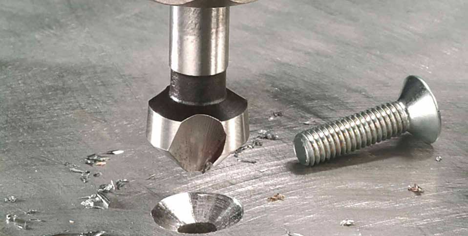
Countersinking in sheet metal involves creating a conical recess in a hole to accommodate the head of a screw in a flush and level manner. At LaserBoost, we perform this process using sharp drill bits, ensuring a precise and clean finish without damaging the material.
> Preparing your file for counterboring
Properly preparing your files for countersinking not only optimizes the process but can also significantly accelerate your production time.
Preparation of 2D files with countersinking
To correctly generate the 2D file for the production of a flat part with countersinking, the hole from which the countersink shape originates meaning the smaller diameter must be drawn. Next, select the countersinking process, specifying both its size and the desired quantity per part to ensure precise and efficient manufacturing. You can add comments or documents to provide more information on which holes should be countersunk.
Preparation of 3D files with countersinking
To correctly generate the 3D file for the production of 3D part with countersinking, the desired countersink shape must be drawn in the 3D file. Next, select the countersinking option, specifying both its size and the desired quantity of countersinking for each part to ensure precise and efficient manufacturing. You can add comments or documents to provide more information on which holes should be countersunk.
> Capabilities of the counterboring process
At LaserBoost, we perform countersinking using precision CNC machines. Your countersinks will be clean and free of burrs.
We offer various methods for countersinking:
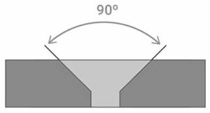
- The Through Countersink mode applies the countersink across the entire material thickness at a 90º angle.
- The Screw Countersink mode (M2, M2.5, M3, etc.) applies the countersink just enough to hide the head of a countersunk screw of the selected size according to the general DIN standard (e.g., DIN 7991 or DIN 965, among others).
- The Custom Countersink mode is done according to the dimensions you need, with a larger diameter (ø) for the chamfer, at a 90º angle. For custom countersinks, we can achieve diameters of up to Ø34mm.
All countersinks are performed at a 90-degree angle.
> Additional Considerations
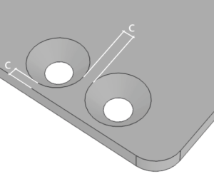
Countersinks close to each other
If your design includes countersinks that are too close to each other or near a cutting or bending geometry, they will be manufactured at your own risk, assuming the possible effects on the final quality and deformation of the part.
To minimize these risks, we recommend reviewing the placement of the countersinks before confirming your order.
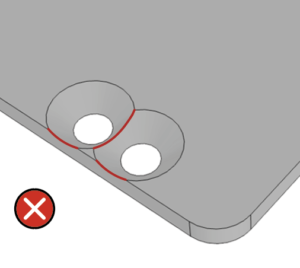
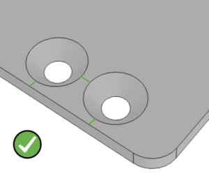
The minimum safety distance (C distance on picture below) between the edge of the countersink and any other geometry of the part must be 2 mm to prevent deformations or defects in the machining process.
Materials with film
In materials with protective film, countersinking may generate chips that can accidentally cause small marks on the material’s surface. At LaserBoost, we apply methods to minimize this effect, but slight marks may appear around the machined hole.
For more details on countersinking tolerances, visit our tolerances section here.
Any questions? The technical team at LaserBoost is at your service to assist with your design and validate that your files are correct for placing an order. Contact us at info@laserboost.com.
About User Guides, Tolerances, and Production Capabilities at LaserBoost
It’s possible to correctly manufacture parts that do not meet the capacities announced here. However, the correct outcome of cutting and/or bending is not guaranteed by LaserBoost if the specifications stated on our website are not met. If a design does not meet any of the tolerances, capacities, or limitations announced, it may still be produced by LaserBoost at the customer’s risk. You can validate the proper manufacturability of your design before placing an order by contacting our technical team at info@laserboost.com.
For more information about the use of our platform, you can visit our Terms and Conditions of Service.
Credit card

| PayPal

| SEPA Transfer

| Bank Transfer – Proforma Invoice
Credit card

Pay Pal

SEPA Instant Transfer

Bank Transfer – Proforma Invoice


